Fabric Cutting Machines: From Electric Knife to CNC
An industrial cutter is more than a blade. Trace how garment cutting moved from hand-guided electric knives to numerical control, vacuum beds and video-assisted plaid alignment.
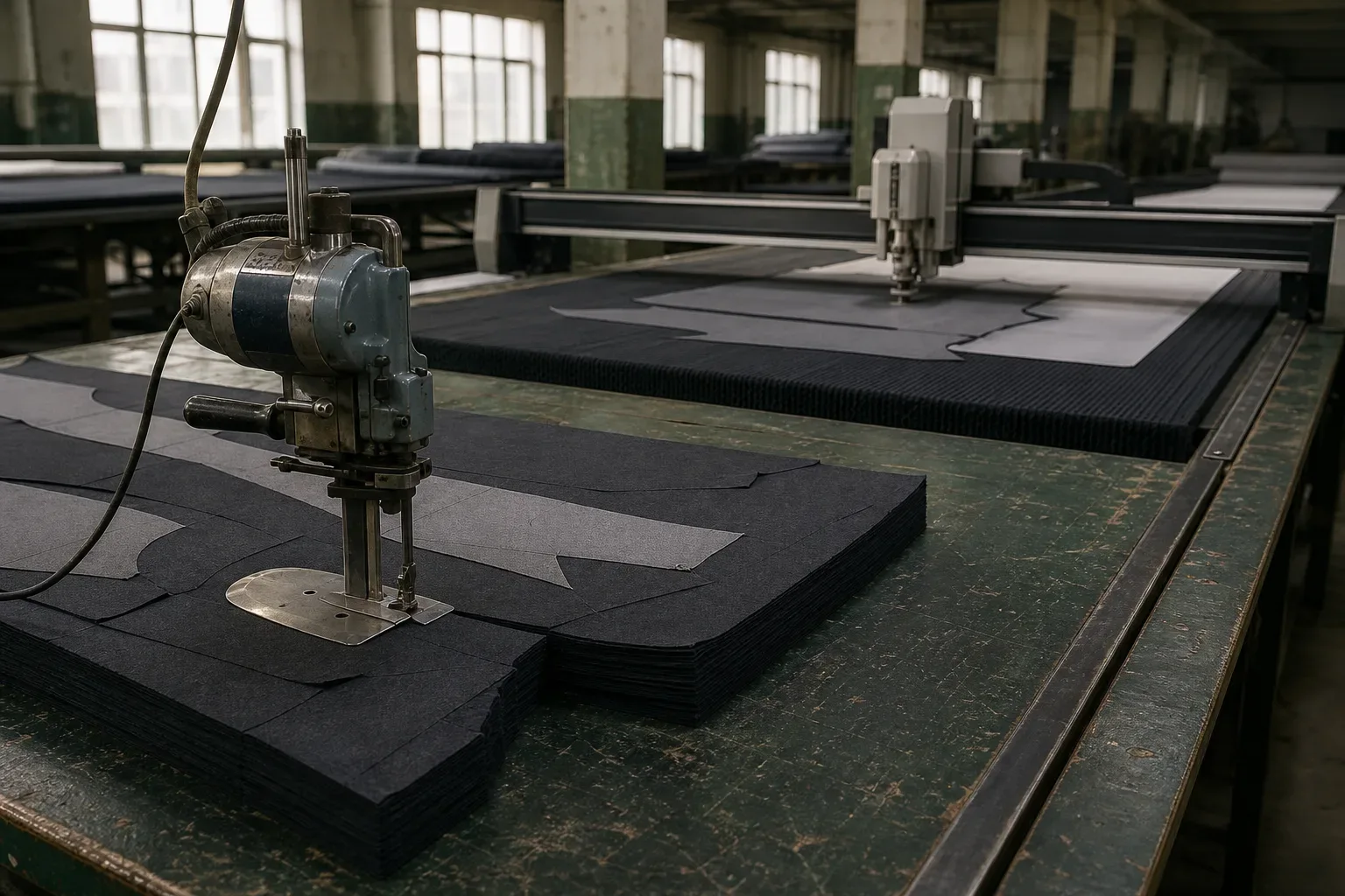
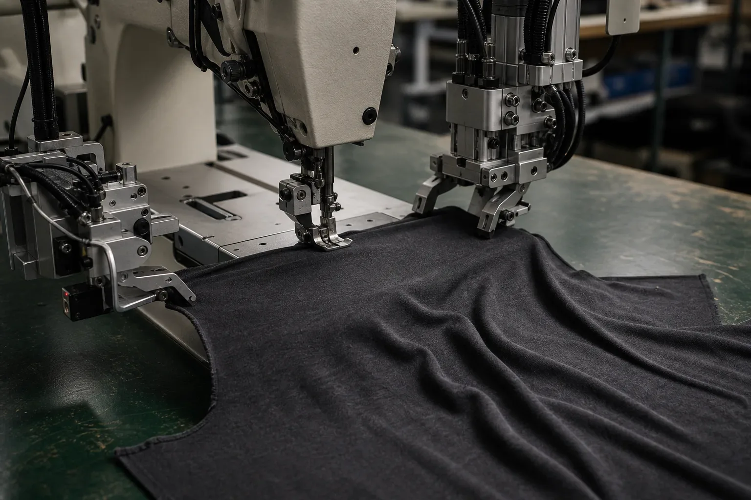
An industrial fabric cutting machine is a blade, a material-support system and a way of controlling the cut path. The blade gets most of the attention, but the other two parts decide whether the bottom ply matches the top one. In an operator-guided straight knife, a person moves the machine through a stack. In an automatic cutter, a controller moves a cutting head across a stabilized table. Add a camera and the printed stripe or plaid can influence where the pattern piece is placed before cutting.
That is the short answer. The longer history is not a clean march from scissors to a fully autonomous factory. Manual and automatic cutters still coexist because a sample, a tall lay and a matched plaid present different jobs. And every date below needs one warning: it marks a cited patent, museum object or company chronology, not the year the whole garment industry adopted the technology.
This is the cutting-room chapter in our machinery series. Upstream, the industrial circular knitting machine turns yarn into jersey. Downstream, sewing robots still struggle with a T-shirt because the stable lay becomes separate, deformable panels. Here, the question is narrower: who controls the knife, and what controls the cloth?
The machine map: which cutter fits which job?
The useful way to classify a fabric cutter is to ask three questions: what moves, how many plies are being handled, and how tightly the path curves. “Automatic” is not a synonym for “best.” A programmed table is powerful when a repeatable marker and stable lay justify the setup. A skilled operator with a portable cutter can make more sense for a sample, short run or unusual piece.
| Tool or control system | What moves | Typical cutting-room role | Main constraint |
|---|---|---|---|
| Straight knife | Operator steers a reciprocating vertical blade and base | Multi-ply lays, including curved garment pieces | Accuracy depends on steering, blade condition and lay stability |
| Round knife | Operator steers a rotating disc and base | Lower lays, straight runs and broad curves | Disc geometry is less suited to tight internal turns |
| Rotary shear | Operator guides a small rotating blade | Portable low-ply cutting | Capacity depends on the model and material |
| Computer-controlled knife | A cutting head moves across an X/Y table | Programmed single-, low- or high-ply cutting, depending on the system | Still requires suitable spreading, hold-down, tool choice and planning |
Current manufacturer catalogs still place manual tools beside computer-controlled systems. That is a vendor taxonomy, not an independent ranking: Eastman, for example, markets both manual and automated cutting families. Apparel-engineering curricula likewise teach several methods rather than one evolutionary ladder.
Perimeter cutting separates panels; pattern marks carry assembly information. The University of Arkansas's open apparel-production workbook distinguishes the outer cutting line from notches and dots used to match pieces or locate construction details. Those marks belong to the cutting-room handoff, but they do not do the blade's job.
Before electricity, the bottleneck was the stack
Ready-to-wear depends on repetition. A factory needs the same sleeve in the planned size ratio, cut consistently across a stack. That lay is multiple plies spread on a table; the marker arranges pattern pieces across the usable width. Stack cutting multiplies output—and any error through the plies.
The Smithsonian's overview of ready-to-wear machinery gives a compact US chronology: long knives replaced shears in cutting rooms in the 1870s, and electric cutting equipment appeared by the 1890s. The important change was not only sharper or faster cutting. It was the ability to reproduce garment parts for mass production.
Flexible cloth is not sheet metal
A metal sheet on a rigid fixture usually keeps its geometry while a tool approaches. Cloth bends, compresses and slides. The pressure of a blade can push the upper plies sideways while the base drags under the lowest ply. A tall lay can therefore be correct at the top and displaced lower down.
Cutting is therefore a systems problem: spread without unwanted tension, register the plies, support them while the knife passes through, then follow the marker accurately. The full chain is in how a T-shirt is made; this article owns cutter history and mechanics, not the release of a completed lay or the disposition of inspected cut parts.
What did the first electric cutters actually change?
Electricity took over the repeated blade stroke before it took over steering. Frank W. Nevens's US patent 372,926, filed July 29, 1887 and issued November 8 that year, describes a portable motor-driven cloth cutter for stacked material. A motor on the carriage drives a vertical reciprocating knife. A thin base passes beneath the bottom ply, and the operator moves the machine along a pattern placed on top of the stack.
The motor supplies the rapid up-and-down work. The person supplies the X/Y path, sees the pattern and corrects the machine. Electrification reduces one physical burden without automating the cutting decision.
The 1887 patent and Eastman's 1888 company date
Eastman Machine dates its own commercial history to 1888 and describes that cutter as the first electric fabric-cutting machine. That “first” is a manufacturer claim and should be read as such. The Nevens patent record is already public in 1887, so the available evidence does not support turning Eastman's wording into an uncontested worldwide priority claim.
The dates can stand together without forcing a winner: an 1887 US patent documents a motor-driven reciprocating cutter; Eastman's company chronology begins with an 1888 commercial machine. They answer different historical questions.
A patent is not an adoption curve
A patent shows what an inventor disclosed and claimed. It does not prove how many machines were built or how quickly a method spread. Patents are strong evidence for architecture and chronology, not universal shop-floor adoption.
The 1907 museum cutter makes the physics visible
A surviving object can explain a design problem more directly than a slogan. The Smithsonian records an industrial cloth cutting machine made in 1907–1908. Its vertical circular blade cuts down into stacked textiles while a thin, round base passes under the lay. The museum describes the geometry as a way to reduce pressure, cloth displacement and resulting error.
That does not establish the first circular cutter, nor does one object prove the design dominated its era. It does show that work holding and downward force were already central engineering concerns. A rotating disc and a reciprocating straight blade attack the stack differently, but both need a path beneath the lowest ply and both can disturb soft material if the lay is poorly prepared.
That distinction survives: round knives suit certain lays and broad curves, while straight knives can negotiate tighter garment outlines. The job selects the geometry.
How numerical control moved the knife
The next major control change was not a new cutting edge. It was converting a marker path into coordinates. The Smithsonian's Gerber Fabric Cutter archive places work on Gerber's S-70 in the late 1960s and describes numerical control applied to garment layout and cutting. In this historical context, numerical control, or NC, is the period-appropriate term.
Gerber and Pearl's US patent 3,548,697 was filed May 5, 1969 and issued December 22, 1970. It describes sheet material supported on a penetrable bed, with relative movement between the cutting tool and material in two coordinates. A controller or computer supplies the signals so the carriage can follow straight and curved paths.
Hand steering has become controlled X/Y motion. “Automatic cutter” still does not mean an autonomous cutting room: people approve the pattern and marker, prepare the lay, select settings, inspect results and preserve bundle identity.
NC then, CNC now
Modern buyers often search for a CNC fabric cutter, and CNC is useful shorthand for a computer-controlled cutting table. It should not be projected backward carelessly. The archival and patent language around the S-70 is numerical control and computer-directed movement. The 1970 patent is a documented architecture milestone, not “the year CNC took over garment factories.”
Why an automatic cutter needs vacuum and a penetrable bed
A perfect coordinate path is useless if the lay moves. A knife also cannot cut through the bottom ply if the table underneath behaves like a kitchen counter. Automatic cutting therefore needs a surface that performs two apparently contradictory jobs: support the material and let the blade enter it.
Gerber and Pearl's US patent 3,765,289, filed in 1971 and issued in 1973, documents one influential solution. A gas-permeable, penetrable bed can be built from upright bristles. Vacuum acts through that surface to hold the lay, sometimes with an impermeable overlay helping seal the stack. The cutting blade penetrates between the bristles while carriages move it in X and Y. Zoned suction can concentrate hold-down where it is needed.
The table acts as both clamp and sacrificial surface. Vacuum restrains material that could slide or lift; bristles support the stack without becoming a solid obstacle.
Planning starts before suction turns on
Work holding does not decide what to cut. Orders still have to become feasible lays: which sizes and quantities go into each spread, how many garment components each lay produces, and how the available bed is used. Shang and colleagues formalized this as a fabric spreading and cutting optimization problem in 2019.
Automation can execute a marker; planning decides whether it produces the required component mix. Yield and setup affect price, but those belong to why factory quotes differ, not to a machine-speed claim here.
Vision alignment: when the print controls the marker
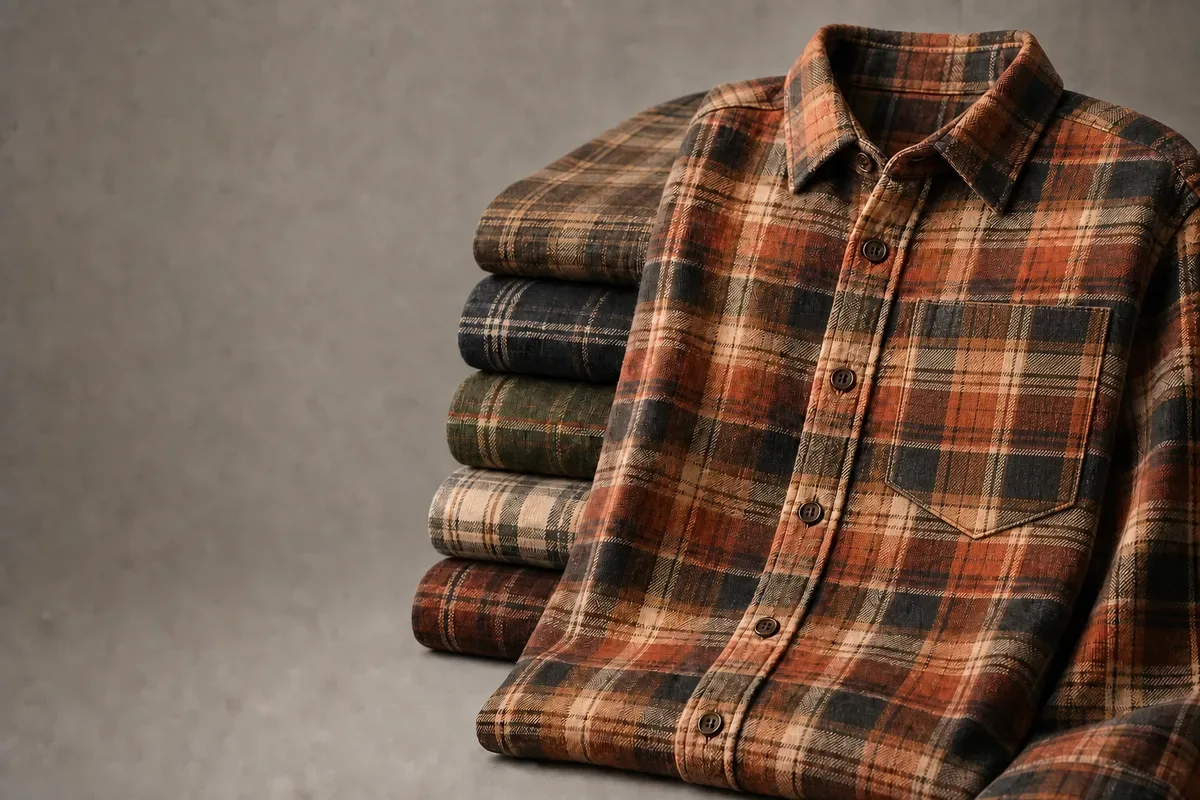
The densest marker is not always correct. On solid fabric, moving pieces closer may improve use. On plaid or stripe, a pocket, placket or seam may need to meet a visible repeat. The quality target changes the nesting problem.
Gerber's US patent 5,333,111, filed May 2, 1991 and issued July 26, 1994, documents computer-assisted pattern alignment using a video subsystem. Its description covers image stability, focus and illumination, comparisons within the captured image, and manual or automatic adjustment of marker pieces to align stripes or plaids.
This is video-assisted alignment or computer vision, not evidence of modern AI. It is also not proof that factories universally adopted vision systems in 1994. The patent date establishes a disclosed system: a camera can make the fabric repeat part of the control loop before the cutter follows its path.
Why a camera can increase acceptable waste
Without a match rule, software may place pieces wherever they nest most densely. With a rule—pocket stripe aligned to body stripe, or left front mirroring right front—pieces may have to move apart. More space can be the correct result because visual continuity, not maximum density, is the approved quality standard.
The machine cannot invent that standard. A buyer and factory must define which seams match, where the reference line sits and what tolerance is acceptable. Our custom flannel manufacturing guide covers the product consequence; the cutter only executes the alignment decision.
What automation still leaves to the cutting room
Automation can control tool motion with great discipline. It does not decide whether a roll has an unacceptable shade shift, whether a knit has relaxed enough to cut, whether a one-way print may be rotated, or whether a recorded material defect must be avoided before the marker runs.
People still define and verify:
- the approved pattern revision and size ratio;
- fabric face, grain, nap and one-way orientation;
- usable width, defects, shade lots and relaxation requirements;
- marker priorities and any stripe, plaid or artwork match points;
- notch, drill and internal-marking requirements;
- bundle labels, quantity reconciliation and remake handling;
- the project quality threshold the cut-panel inspector will apply.
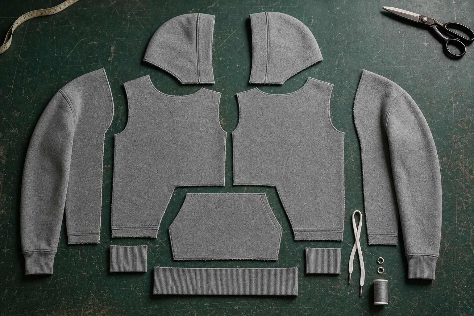
A hoodie lay can contain bodies, sleeves, hood pieces, pocket, facings and rib templates; see the parts of a hoodie factory guide for the component map. One piece in the wrong size, direction or shade lot can make a perfectly followed path produce the wrong bundle.
These are cutting inputs and control responsibilities, not this machinery article's cut-part acceptance workflow. Once cutting is complete, route ragged or hardened edges, ply-to-ply outline drift, missing or misplaced notches/drills, bundle discrepancies and recut evidence to the garment-cutting-defects guide.
What a buyer should specify
A useful cutting brief does not name a machine brand. It identifies the approved pattern, fabric face and direction, grainline, nap or print orientation, match points, notches, drill locations, quantity by size and color, and the rule for separating lots. Pattern-piece vocabulary is mapped in our T-shirt anatomy guide; putting those names into a production-ready tech pack makes the cutting instructions auditable.
That is the boundary between machine capability and production judgment. Machinery repeats the rule it receives. A factory still has to make sure the rule describes the garment the buyer approved.
The real history is control
The blade is only one thread. An 1887 patent documents motorized reciprocation under hand steering; Eastman dates its commercial story to 1888. A 1907–1908 museum object exposes the ply-displacement problem. A 1969 filing turns the marker into X/Y control signals, a 1973 patent documents vacuum hold-down, and a 1994 patent documents video-assisted alignment.
None of those dates is an industry-wide adoption date. Together they show four control problems being separated over time: powering the edge, steering the path, holding the lay and aligning the visible fabric. The buyer's task has not disappeared. Specify the pattern, direction, match rules, internal marks and bundle logic before asking any cutter—manual or automatic—to repeat them.
For a project-specific review, send the current tech pack, fabric construction, size breakdown and artwork or match requirements. Those inputs determine the cutting plan long before machine selection becomes the interesting question.
FAQ
What is an industrial fabric cutting machine? It is a system that separates fabric along a planned path using a cutting tool, material support and some form of path control. A portable straight knife is steered by an operator. A computer-controlled cutter moves a head across an X/Y table and usually integrates hold-down suited to its lay.
What is the difference between a straight knife and a CNC fabric cutter? A straight knife has a vertical reciprocating blade on a portable base; the operator pushes it through the lay and follows the marker. A CNC fabric cutter uses programmed coordinates to move the tool relative to a stabilized table. Both still depend on correct spreading, patterns, blade or tool condition and inspection.
Who invented the electric fabric-cutting machine? The evidence does not support a simple unqualified winner. Frank W. Nevens received US patent 372,926 for a motor-driven reciprocating cloth cutter in 1887. Eastman Machine dates its own commercial cutter to 1888 and calls it the first. The patent record and company claim should be reported separately.
How does an automatic cutter keep layers from moving? One documented architecture uses vacuum through a gas-permeable, penetrable bed, with bristles supporting the lay while allowing the blade to enter. An impermeable overlay can help seal the stack. US patent 3,765,289, issued in 1973, describes this approach; that date is a patent milestone, not a universal adoption date.
Can an automatic cutter match stripes and plaids? Video-assisted systems can capture the fabric repeat and help adjust marker pieces before cutting. The buyer and factory still have to define which points must match and the acceptable tolerance. A 1994 Gerber patent documents this as image processing and computer-assisted alignment, not modern AI.
References
- Smithsonian National Museum of American History, “More for Everyone” — museum overview of stack cutting, long knives and early electric equipment in ready-to-wear production.
- Frank W. Nevens, US 372,926, “Cloth-cutting machine” — filed and issued in 1887; primary record for the motor, reciprocating knife, base and operator-guided pattern following.
- Eastman Machine, “Our History” — first-party company chronology and its attributed 1888 “first” claim.
- Smithsonian, “Industrial Cloth Cutting Machine, 1907–1908” — museum object record for the vertical circular blade, base and ply-displacement problem.
- Smithsonian, Gerber Fabric Cutter Video Documentation, NMAH.AC.0609 — archival context for the S-70 and numerical control in garment layout and cutting.
- Gerber and Pearl, US 3,548,697, “Apparatus for cutting sheet material” — filed in 1969 and issued in 1970; primary record for controller-driven X/Y cutting over a penetrable bed.
- Gerber and Pearl, US 3,765,289, “Vacuum hold-down apparatus” — filed in 1971 and issued in 1973; primary record for vacuum, bristles and a penetrable support.
- Craig L. Chaiken and John A. Fecteau, US 5,333,111, “Garment cutting system having computer assisted pattern alignment” (original assignee: Gerber Garment Technology, Inc.) — filed in 1991 and issued in 1994; primary record for video-assisted stripe and plaid alignment.
- Shang et al., “A Heuristic Algorithm for the Fabric Spreading and Cutting Problem in Apparel Factories”, IEEE/CAA Journal of Automatica Sinica (2019) — peer-reviewed formulation of lay planning as an optimization problem.
- K.S.Rangasamy College of Technology, B.Tech Textile Technology curriculum — academic taxonomy check for straight knife, round knife, band knife and computer-controlled cutting; the autonomous program is affiliated to Anna University.
- University of Arkansas, “Pattern Symbols,” Introduction to Apparel Production Workbook — open educational reference for cutting lines, notches, dots and construction matching.